
Adults onlyArduino NanoLevel 1/3
Inverter Backup Timer
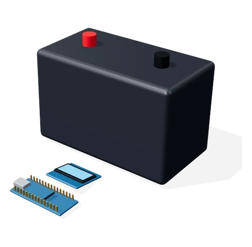
A voltage sensor reads the inverter battery and an OLED shows how long the backup will last, live.
Adults only
Involves a high-current inverter battery.
Not for children. Build at your own risk.
Strictly follow the description given with this video.
Video
The video link will be added here soon.
How it works
- The 0–25V sensor divides the battery voltage down to a safe level.
- The Nano reads it on A0.
- It estimates the charge left and the backup time at the current load.
- The OLED shows the time left; switch on more load and it drops.
Parts you need
Kit for this projectPrice on request
Get the kitWiring
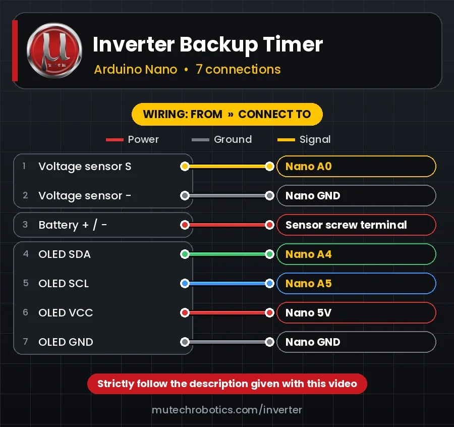
PowerGroundSignal
| # | From | Connect to |
|---|---|---|
| 1 Signal | Voltage sensor S | Nano A0 |
| 2 Ground | Voltage sensor − | Nano GND |
| 3 Power | Battery + / − | Sensor screw terminal |
| 4 Signal | OLED SDA | Nano A4 |
| 5 Signal | OLED SCL | Nano A5 |
| 6 Power | OLED VCC | Nano 5V |
| 7 Ground | OLED GND | Nano GND |
3D print files
This project has no 3D-printed parts.
Code
The tested Arduino / ESP32 code for this project will be posted here, ready to copy.